Saturday, November 26, 2016

Week 10


The Design Team was able to obtain a T-Valve that would allow the inflation of the two balloons simultaneously. When obtaining this device the Design Team was able to complete the circuit for the Floating Car Project. Below is a video of the mechanism at work. When testing the system the Design Team noticed that there was a leak in the connection between the tube and the balloon. This was due to the fact that the seal created with the electric tape was not laid down properly. After noticing this deification the Design Team corrected it and retested the machine. During the remainder of the week the Design Team focused on finalizing their project so that it would be ready for the final presentation. Now that the team as built all of their part all they need to do is assemble it and adjust any minor errors.

Fully connected circuit attached to balloon testing for inflation
Video of balloon getting inflated from the entire operating system.


Sunday, November 20, 2016

Week 9

During this week the Design Team worked on redesigning their frame. The initial frame that the had come up with on Creo if printed would have been to heavy and inconvenient for the user to apply to their car. Conceptually, the team thought of a new design that can be attached with ease to any car without having to go to a mechanic. The idea of the design is that any buyer can attached the mechanism on their own car at home without the need of a professional technician. For this reason the team decided to go with a detachable X-frame. With this system the user can attach the four corners of the frame towards the wheels of the car, thus creating one big X-shaped piece. Towards the middle of the frame in cylindrical containers will be where the nylon pouches will be kept. Once the water sensors detect a high level of water on the car they will activate the CO@ valves, which will then inflate the nylon pouches. These pouches will extend out from beneath the car and shape up around the perimeter of the car. In this manner the car will not have to worry from tipping over from the activation of the inflating pouches.

X-Shaped Frame Created with Creo

X-Shaped Frame Attached to Bottom of Car
View from Above the Car 


Sideview of Frame Attached to the Car

The design team also worked on finalizing their Final Design Proposal. After receiving comments and reviews from their TA, they added what need to be fixed on the final proposal.

Monday, November 14, 2016

Week 8

During this week the Design Team focused on building the frame for the Floating Car Project. Do to a backup with the 3-D printing, it was decided that Kinex pieces were the best alternative. The lab offers various sizes and types of Kinex pieces, thus allowing the Design Team to create a well suited car frame. The design of the frame was built in a manner that the balloons and CO2 cartridges can be maintained by the frame without dispersing and remain in contact with the device. The longer red Kinex pieces were used, instead of the yellow Kinex pieces to assure enough room when the balloons are fully inflated by the CO2 cartridges. Reinforcing structures were added on to the extremities of the frame in order to create a more solid structure. The balloons will be placed above the green Kinex pieces and tied together to the ends of the frame. With this kept in mind the CO2 cartridges will be placed above the car with all of the other sensory mechanisms.

Bottom View of the Frame 
Upper View of the Frame


During week 8 the Design Team finalized their Design Proposal and submitted it for review. Within this proposal they spoke more about how the Relay switch will come to work in the mechanism.


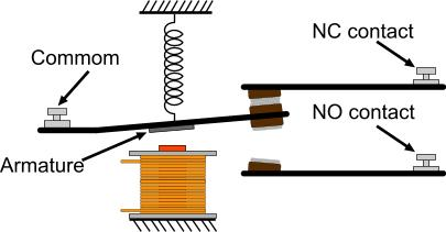
A relay switch will be activate when the water sensor reaches a certain value. The relay switch when activated will supply power to the solenoid valve, opening the valve and allowing CO2 to fill the balloons. Three components of Relay switch are Common, Normally closed and Normally open. For this circuit, common will be connected to the ground and NO, normally open, will be connected to the solenoid, a 12V battery will be used to power the solenoid. NC, normally closed, will remain unplugged since arduino will only activate relay if the water level is reached.   A magnetic field is created when current is flown through the circuit which pulls the contact and changes its position, which enables the circuit.
Relay Switch Compatible With Arduino

Function of a Relay Switch

Sunday, November 6, 2016

Week 7

The Design Team conducted various test on the Arduino board to see if the water sensor responded efficiently to being wet. By running the program the group noticed that as the sensor was immersed more and more by water the values started to increase. In order to assure that the mechanism does not activate at a low water level the sensor needs to be placed on a section of the car where if the water level were to surpass it there would be serious damage to the car. 


Left corner blue Arduino board, inside cup water sensor detecting data outputs
 The team also found the model car that they decided to test their mechanism on. A frame will be created on CREO and printed out through a 3-D printer. Because the RC car has a smooth surface the frame will have to be glued on as it would be difficult to find connecting points without obstructing the frame. The car is to give the observer a visual representation of how the mechanism would work in a real life scenario.

Blue RC car on which frame will be attached