Saturday, November 26, 2016

Week 10


The Design Team was able to obtain a T-Valve that would allow the inflation of the two balloons simultaneously. When obtaining this device the Design Team was able to complete the circuit for the Floating Car Project. Below is a video of the mechanism at work. When testing the system the Design Team noticed that there was a leak in the connection between the tube and the balloon. This was due to the fact that the seal created with the electric tape was not laid down properly. After noticing this deification the Design Team corrected it and retested the machine. During the remainder of the week the Design Team focused on finalizing their project so that it would be ready for the final presentation. Now that the team as built all of their part all they need to do is assemble it and adjust any minor errors.

Fully connected circuit attached to balloon testing for inflation
Video of balloon getting inflated from the entire operating system.


Sunday, November 20, 2016

Week 9

During this week the Design Team worked on redesigning their frame. The initial frame that the had come up with on Creo if printed would have been to heavy and inconvenient for the user to apply to their car. Conceptually, the team thought of a new design that can be attached with ease to any car without having to go to a mechanic. The idea of the design is that any buyer can attached the mechanism on their own car at home without the need of a professional technician. For this reason the team decided to go with a detachable X-frame. With this system the user can attach the four corners of the frame towards the wheels of the car, thus creating one big X-shaped piece. Towards the middle of the frame in cylindrical containers will be where the nylon pouches will be kept. Once the water sensors detect a high level of water on the car they will activate the CO@ valves, which will then inflate the nylon pouches. These pouches will extend out from beneath the car and shape up around the perimeter of the car. In this manner the car will not have to worry from tipping over from the activation of the inflating pouches.

X-Shaped Frame Created with Creo

X-Shaped Frame Attached to Bottom of Car
View from Above the Car 


Sideview of Frame Attached to the Car

The design team also worked on finalizing their Final Design Proposal. After receiving comments and reviews from their TA, they added what need to be fixed on the final proposal.

Monday, November 14, 2016

Week 8

During this week the Design Team focused on building the frame for the Floating Car Project. Do to a backup with the 3-D printing, it was decided that Kinex pieces were the best alternative. The lab offers various sizes and types of Kinex pieces, thus allowing the Design Team to create a well suited car frame. The design of the frame was built in a manner that the balloons and CO2 cartridges can be maintained by the frame without dispersing and remain in contact with the device. The longer red Kinex pieces were used, instead of the yellow Kinex pieces to assure enough room when the balloons are fully inflated by the CO2 cartridges. Reinforcing structures were added on to the extremities of the frame in order to create a more solid structure. The balloons will be placed above the green Kinex pieces and tied together to the ends of the frame. With this kept in mind the CO2 cartridges will be placed above the car with all of the other sensory mechanisms.

Bottom View of the Frame 
Upper View of the Frame


During week 8 the Design Team finalized their Design Proposal and submitted it for review. Within this proposal they spoke more about how the Relay switch will come to work in the mechanism.


A relay switch will be activate when the water sensor reaches a certain value. The relay switch when activated will supply power to the solenoid valve, opening the valve and allowing CO2 to fill the balloons. Three components of Relay switch are Common, Normally closed and Normally open. For this circuit, common will be connected to the ground and NO, normally open, will be connected to the solenoid, a 12V battery will be used to power the solenoid. NC, normally closed, will remain unplugged since arduino will only activate relay if the water level is reached.   A magnetic field is created when current is flown through the circuit which pulls the contact and changes its position, which enables the circuit.
Relay Switch Compatible With Arduino

Function of a Relay Switch

Sunday, November 6, 2016

Week 7

The Design Team conducted various test on the Arduino board to see if the water sensor responded efficiently to being wet. By running the program the group noticed that as the sensor was immersed more and more by water the values started to increase. In order to assure that the mechanism does not activate at a low water level the sensor needs to be placed on a section of the car where if the water level were to surpass it there would be serious damage to the car. 


Left corner blue Arduino board, inside cup water sensor detecting data outputs
 The team also found the model car that they decided to test their mechanism on. A frame will be created on CREO and printed out through a 3-D printer. Because the RC car has a smooth surface the frame will have to be glued on as it would be difficult to find connecting points without obstructing the frame. The car is to give the observer a visual representation of how the mechanism would work in a real life scenario.

Blue RC car on which frame will be attached

Monday, October 31, 2016

Project Timeline and Budget

Below is the Timeline and Budget for the Floating Car Project created by the Design Team

Timeline

The timeline of the Design Project will be divided into theory, experimental, and application. For the first two weeks, the design team will conduct theoretical research for applying these concepts to a real-life scenario. After a sufficient amount of theoretical data has been collected the Design team will begin conducting experimental trials through virtual simulation and mechanical designs. When the team believes to have created a device that represents their conceptual design the will assemble it all together and give a final deliverable on the device.


Budget

In order to create this project some of the materials needed to be purchased by the design team. The water sensor was a key piece as it activated the entire process when triggered by a certain water level. CO2 canisters, rocket balloons, pressure regulator, and the Relay made up the floatation device. All of these elements put together comprised the floatation mechanism and then were added to the frame that finally was attached to the bottom of the RC car. Thanks to resources from the lab the budget cost was not too high as materials such as the Arduino board were provided by the class instructor.

Category
Projected Cost
Water Sensor (2 piece)
                                 $3.50
1/10 Scale Car
                                      $45
CO2 Canisters
                                   $10
Rocket Balloons
                                      $10
Anchoring Materials
$5
Pressure Regulator
$19.90
Relay 5V (2 pieces)
$7.5
Total
$100.90
3-D printing and Arduino board were provided by class instructor. 

Week 6

The Design Team work on developing a circuit to activate their flaotion Devation. They used Relays, which are electromagnetic switchs that can work with small currents to activate (turn on and off)  larger electric circuits. For the Floating Car Project the team will be using a 5V relay switch that will be connected to an arduino board starting the flow of the mechanism. A water sensor will always be attached to the adruino board and will be coded to detect a certain amount of water level before activatiing.


https://www.quora.com/How-do-I-make-an-automatic-AC-switch-using-Arduino-Uno-which-can-turn-on-and-off-at-a-particular-set-time

Monday, October 24, 2016


Basic Idea of Equipments Used


Arduino Board

Arduino is an open-source project that created microcontroller-based kits for building digital devices and interactive objects that can sense and control physical devices. The project is based on microcontroller board designs, produced by several vendors, using various microcontrollers.


Arduino Board


Connecting arduino board to computer


Solenoid  Valve

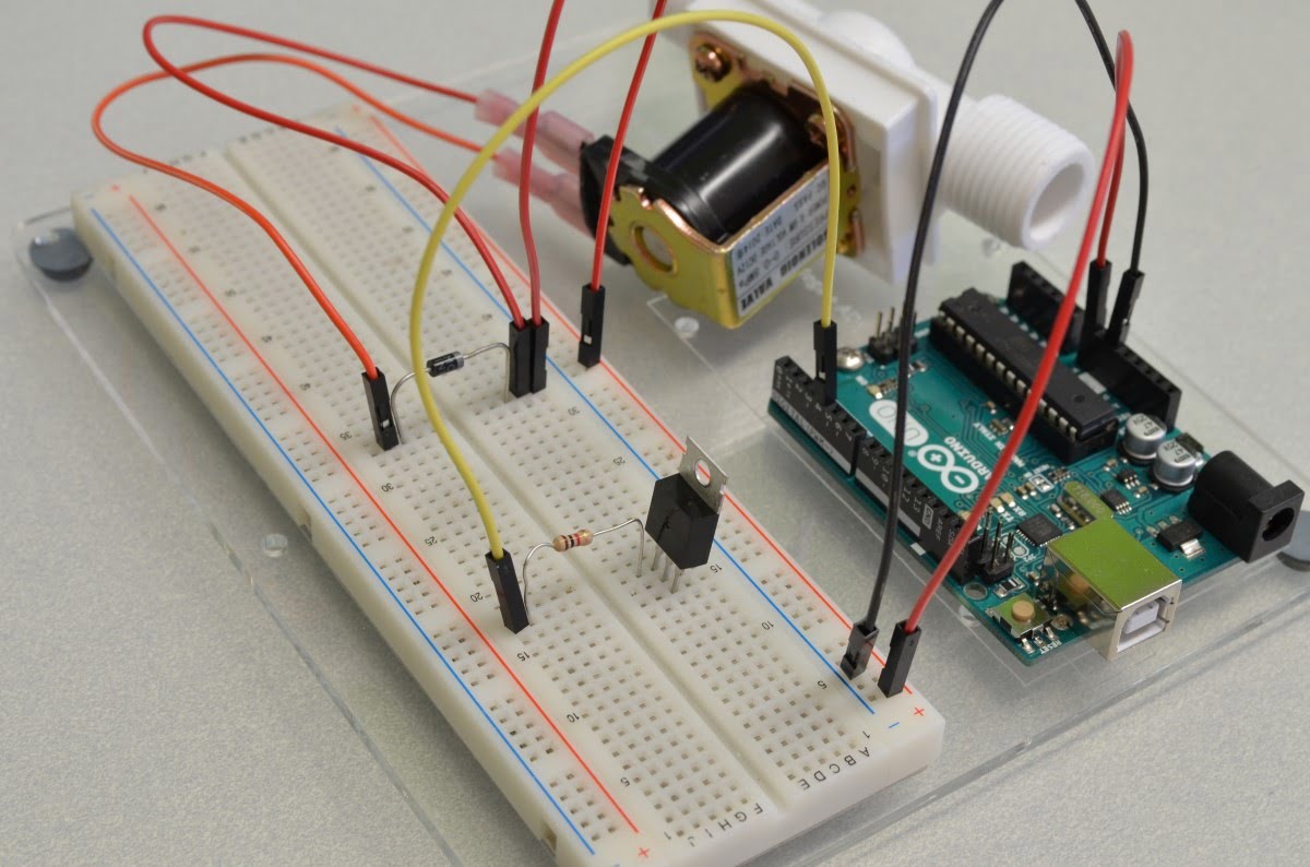
solenoid valve is an electromechanically operated valve. The valve is controlled by an electric current through a solenoid: in the case of a two-port valve the flow is switched on or off; in the case of a three-port valve, the outflow is switched between the two outlet ports.

Solenoid valve and bread board

Water Level Sensor

Water-level indicator is used to indicate the level of water in over head tank, by using this we can avoid the overflow of water, and at any time we can know the level of water in tank, it has a simple circuit .


Image result for water level sensors compatible with arduino board
Water level sensor connected to arduino


Carbon dioxide Catridges

It stores and releases compressed  carbon Dioxide on demand. CO2 cartridges are small metal containers, about the size of your thumb, that hold highly pressurized CO2 (carbon dioxide) gas.
Carbon Dioxide Catridges

Relay Switch

A relay is an electromagnetic switch operated by a relatively small electric current that can turn on or off a much larger electric current. The relay switch will be activated when the water sensor reaches a certain value. The relay switch, when activated, will supply power to the solenoid valve, opening the valve and allowing CO2 to fill the balloons. Three components of Relay switch are Common, Normally closed and Normally open. For this circuit, common will be connected to the ground and NO, normally open, will be connected to the solenoid, a 12V battery will be used to power the solenoid. NC, normally closed, will remain unplugged since Arduino will only activate relay if the water level is reached.   A magnetic field is created when current is flown through the circuit which pulls the contact and changes its position, which enables the circuit.

Relay Switch
Function of Relay Switch compatible with Arduino


Sunday, October 23, 2016

Week 5

     The Design team agreed on what parts, sensors, and supplies that would be needed to construct the prototype this week. During the scheduled lab session the team finalized the role of each part and how they would work in conjunction with each other.

Parts/Supplies/Sensors:

Model Car:
     The 1:10 scale car we found represents the 1:1 scale car's volume and not necessarily the weight. It is still being decided if the team will try and match the weight in terms of scale since the time constraints and budget would limit these factors of producing a truly accurate 1:10 scale car. The car will act as the test subject for the prototype. Here is an image of the car the team will order.
 
Water Level Sensor:
     The water level sensor is the first tool the flotation device will utilize to trigger the inflation device. It will be wired and controlled by the Arduino board. The water level sensor detects the water by acting as a pressure sensor so once it is submerged it will send a signal to the Arduino board that the pressure has changed. It will be configured to send a signal only once it is submerged in water in order to decrease false deployments of the flotation device. It will be mounted somewhere under the model car so that it can easily detect a rising water level.

Arduino Board:
    The Arduino board acts as the main controller for the prototype and receives, interprets and sends signals so that everything can interact with each other. The Arduino board is essentially the brain of the prototype. Since the Arduino board is a very critical component to the prototype it will have to be enclosed on top of or inside of the model car in order to keep it from coming in contact with the water. The board will receive input from the water level sensor interpret the signal and in return send a signal to the CO2 cartridge valve that will release the CO2 inflating the balloons.

CO2 Cartridges
     These will provide a small and compact storage for compressed CO2 that will be mounted to the prototype's frame or directly to the model. Releasing the stored CO2 will inflate the balloons creating enough buoyancy to support the model car above water. The amount of cartridges required to supply the model car with enough buoyancy  is still being determined since we do not have the actual weight of the model car.

CO2 Cartridge Valve(s)
     The valves will be wired to the Arduino board in order to release the CO2 once the water sensor sends a signal to the Arduino board. With the actual weight of the model car being unknown and the amount of cartridges needed to supply enough buoyancy, the team currently has  not determined how many valves that will be needed. It is speculated that a minimum of 2 valves will be needed in order to balance the model car and prevent it from tipping over. 

Balloons
     The balloons will be what holds the CO2 in an even manner so the car is floating on a stable platform. The balloons will be securely attached to the valves. The elongated balloons are the most practical because they and lay parallel to the car. offering the most stability.

The Frame
     The frame will be designed and 3D printed to custom fit the model car. Although we have the dimensions of the model car. The placement of wheels is a variable that needs to be taken into consideration and the team cannot print the current frame design until the measurements of the car have been taken.

Week 4

During this week the Design Team received feedback on comments regarding what they should improve with their Design Proposal. The Design Team went over their proposal and reviewed what needed to be corrected.

Below are some of the major changes done to the Design Proposal.

The abstract did not have a concrete reference to where the team got most of their information from, that is why references from the national weather channel were added.

  • "According to thewheatherchannel.com during the time of flash floods a car can easily be carried away by just two feet of water."
It was noted that in the introduction the Design Team did not clarify why they decided to use certain materials and why these materials would be essential to the project. To clarify the project the Design Team added a basic framework of the steps that it will take to create the device.

  • "The project will comprise of three distinct areas; frame, sensor, and flotation. The frame will serve to house the method of floatation, likely vinyl bags, attache to a 1/10th model car, and anchor the car to the ground keeping it from floating uncontrolled and possibly causing damage. A sensor will be used to detect a damaging water level and activate a regulator attached to CO2 cartridge(s) filling the floatation bags allowing the car to remain above a damaging water level. Each area provides its own set of distinct challenges including sensor placement, frame design and keeping the car balanced while floating."
Since it was unclear whether the team was going to build the device to real size or just a to scale prototype they clarified it in their edited proposal.
  • "The goal of the Design Project is to create a 1/10 scale size device that could then be applied to a real life scenario." 
In order to give a better idea of the type of sensor that the Design Team will be building they added a basic Water Level Diagram Circuit that can detect when there is an overflow in water. The Design Team will incorporate the concepts of this sensor into their device in order to activate the flotation devices for the mechanism.
                                                                           

The Design Team also added an image of a possible frame that they could use for the foundation of the floatation device. 
                                                                                     

During this week the Design Team was also able to create a to scale model of the car that they will be using through Solid Works.

Week 3

After conducting thorough research on how to create a floatation device for a car the Design Team wrote up a Design Proposal Explaining the project and how they intend to create this device.

ENGR 103 - Fall 2016
Freshman Engineering Design Lab
FCP (Floating Car Project)
Project Design Proposal

Date Submitted: October 03, 2016
Group Members          
Salomon Jose, sj692@drexel.ed
Keyur Patel, khp34@drexel.edu
       Antonio Tartaglia, at856@drexel.edu
      Micah Watson, mrw83@drexel.edu
Aaron Zehm, amz52@drexel.edu


Technical Advisor            Mr. Marco Janko
Abstract:
Millions of dollars worth of damage is caused by floods every year. Floods and flash floods happen in all 50 states often bringing walls of water 10 to 20 feet high.  According to thewheatherchannel.com during the time of flash floods a car can easily be carried away by just two feet of water. Strong musty odor in interior or luggage compartment¸ surface rust, dampness of upholstered components, mud or sludge build-up¸ rust on underbody and chassis components¸ mud or sludge build-up inside components, high water marks on door panels and lenses of head and tail lamps¸ deposit of debris etc are all major problems caused by floods to a car.


This calls for a new technology to protect our cars. A technology that can help the car to float over the water but still remain anchored to the ground so that the damage to the car is reduced without endangering other people’s life.


Technical challenges we face are weight distribution of the car, design of the mechanism for anchoring the car and stabilising the car.Major tasks include design of frame, circuits and anchoring mechanisms,3-D printing and fabrication of components,assembling and testing the device..


At the conclusion of the project, a design will be simulated which will reduce the cost to damage that occurs during the flooding. A Portable flotation design frame will be created for a car with an even weight distribution. This flotation device will be activated when a certain water level is reached using sensors.

1.  Introduction


As flood rates continue to increase throughout regions of the United States one of the primary cost on individuals is the loss of their car’s, due to water damage. At the conclusion of the project the Design team will  have produced a conceptual prototype that will demonstrate the viability of the project on a full scale car. The project will comprise of three distinct areas; frame, sensor, and flotation. The frame will serve to house the method of floatation, likely vinyl bags, attache to a 1/10th model car, and anchor the car to the ground keeping it from floating uncontrolled and possibly causing damage. A sensor will be used to detect a damaging water level and activate a regulator attached to CO2 cartridge(s) filling the floatation bags allowing the car to remain above a damaging water level. Each area provides its own set of distinct challenges including sensor placement, frame design and keeping the car balanced while floating. At the conclusion of the project, team members will have gained a familiarity with the 3D design necessary to create the required parts, structure design for the frame, and basic circuit design necessary for the sensor and regulator.


2.  Deliverables


At the conclusion of the project, a design will be created that will reduce the cost to damage that occurs during floods. A Portable flotation design frame will be built for mid-sized cars such as sedans. Portable floatation devices can be added to the car when in emergency or any flood advisory is posted.  This flotation device will be activated when a certain water level is reached using sensor technology.


3. Technical Activities


The goal of the Design Project is to create a 1/10 scale size device that could be applied in a real life scenario. In order to do this the Design project will be broken up into three major sections: the frame, the sensors, and the flotation devices. These three components will then be combined into making one optimal mechanism with the sole purpose of assuring no water damage to a car in case of a flood. Through conceptual designs and tested virtual simulations the design team will be able to efficiently produce a balanced product that could save thousands of dollars towards car owners.

3.1 The Frame

Knowing that not all cars have the same length and width dimension creating a frame that could be utilized as “one size fits all” would be extremely expensive. In order to assure the cheapest and most convenient outcome the frame will be modeled to fit a standard mid-size compact car, better known as a sedan, as they are one of the most common car models on the market. Balance is key and assuring a proper weight distribution for the frame distributed throughout the car will provide a safer environment when the floatation device is activated.


Reference Car Frame


3.2 The Flotation Devices


The primary source for the mechanisms’ flotation will be CO2 cartridges, which will be placed in a waterproof pouch that as it inflates will activate the flotation mechanism . These cartridges will be distributed throughout the car according to the different areas of weight distribution. The problem the design team will be facing is the fact that most cars do not have an even weight distribution. The majority of the time the heaviest area of the car is located where the engine is. In order to completely balance the car a proportional distribution of cartridges vs weight will be created.


3.3 The Sensors


To detect the water level and activate the floatation device (Co2 cartilage) we will use a sensor. The design team will take the ideas of a traditional water level sensor mechanism and adapt it to the personalized flotation device. The problem that the team will be facing here is the placement of the water sensor so that it does not get activated with the rain water. This sensor works on the principle of pressure which states pressure is equal to ( density x gravity x height).       


3-D Design Made with Solid Works

4           Project Timeline

The timeline of the Design Project will be divided into theory, experimental, and application. For the first two weeks the design team will conduct theoretical research for applying these concepts to a real life scenario. After a sufficient amount of theoretical data has been collected the Design team will begin conducting experimental trials through virtual simulation and mechanical designs. When the team believes to have created a device that represents their conceptual design the will assemble it all together and give a final deliverable on the device.


Week
Task
1
2
3
4
5
6
7
8
9
10
Literature study
x
x
3-D Design
x
x
x
x
x
Mechanical Design
x
x
x
x
x
System integration
x
x
x
Testing
x
x
x
Final report preparation
x
x
x
Table 1: FCP Design Project Timeline.


5.  Facilities and Resources


Facilities:


The Hagerty library will be where the design team will meet to discuss the project’s goals and create the design proposal along with anything else that doesn’t require working on the physical aspect of the project.


Most of the collaboration will be conducted during the lab session because of the tools and resources available to us at time.


Resources:
  • A one tenth scale model car will be used to conduct our project on. It will serve as the basis for how the prototype will interact with a semi-realistic model.
  • The frame of the car will be 3D printed (rapid-prototyping machine) so that we can have it custom made to fit the car and work to the best of our ability.
  • Creating or purchasing a sensor to detect water in order to deploy the flotation device.
  • Utilizing machine shop tools in order to assemble the prototype.
  • A water tank for conducting tests for the prototype in the appropriate scenarios  


6.  Expertise


The design team is composed of people with all different types of technical expertise. Amongst the design team we have a two Mechanical Engineering majors, two Computer Engineering majors, and one Civil Engineering major. With all of these different backgrounds we are all able to give different and resourceful impacts for the production of the final design.


  • Computer Programming (C++, Python, Matlab) - For retrieving data from real life scenario
  • Knowledge of basic circuit theory - For creation of Water sensor
  • Circuit Design - For creation of Water sensor
  • 3D - Design (AutoCad, Creo, Inventor, Solidworks,Solid edge,CATIA) - For virtual simulation
  • Use of machine tools - For building of device


7.  Budget


Category
Projected Cost
Water Sensor
                                 $5
1/10 Scale Car
                                      $45
CO2 Canisters
                                   $10
Waterproof Pouches
                                      $40
Anchoring Materials
$5
Total
$105

Table 2: FCP Design Project Budget.

7.1 Water Sensor

The water sensors are key into activating the entire process to start the floatation of the car. As the water exceeds a certain level the sensors will detect the water and will be the starting point for the device to start working.


7.2 1/10 Scale Car


The model car will be the main piece of the conceptual design. The other components of the device, frame, sensor, and . Will be attached to the model car to demonstrate the viability of the device.  


7.3 CO2 Canisters


The C02 canisters will activate as soon as the water sensors go off. These canisters will then inflate the pouches that they are placed in allowing the car to start floating.


7.4  Waterproof Pouches


The Waterproof Pouches will be containing the CO2 canisters that when the sensors activate will inflate and allow the car to float. These pouches will be securely attached to the frame assuring that the entire mechanism works as one unit.
7.5 Attachment devices

After the car has started to float and the mechanism has been fully activated attachment devices will deploy from the frame acting as an anchor for the car. This will stabilize the car and prevent it from floating away.